
Grounding Standards for Camera Systems: CCTV and PoE Technical Guide
How should camera systems be grounded? We examine the technical aspects of protective grounding, equipotential bonding, grounding resistance, SPDs and IEC standards in IP cameras, PoE switches, CCTV poles, metal cabinets and NVR systems.
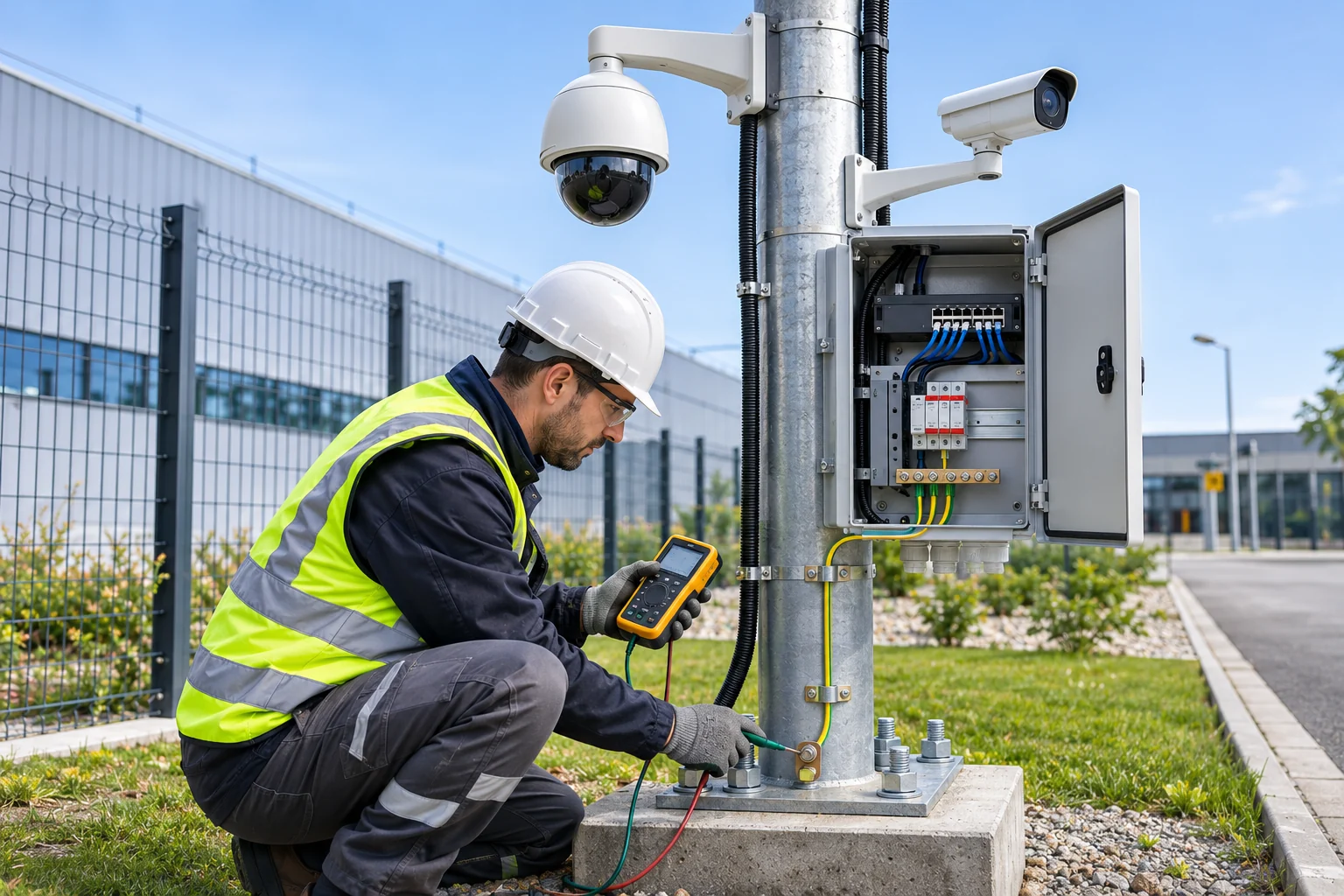
Grounding in security camera systems is one of the fundamental electrical installation practices used to ensure electrical safety, protect people from hazardous touch voltages, and, when properly designed, help protect electronic equipment against electromagnetic effects and overvoltages.
IP cameras installed outdoors, metal camera poles, PoE switches, outdoor field panels, NVR recorders and long-distance communication lines should be carefully assessed for electrical safety.
Incorrect grounding practices can cause electric-shock hazards, equipment damage, communication problems, and the transfer of lightning-induced transient overvoltages between different systems.
Therefore, proper grounding in camera systems is not simply a matter of connecting a wire to a metal pole or driving an electrode into the ground. Protective grounding, equipotential bonding, the characteristics of the supply system, fault-protection arrangements and lightning-protection measures must be designed together.
What Is Grounding in Camera Systems?
Grounding is the connection of designated conductive parts and system points in an electrical installation to an appropriate earthing arrangement.
Grounding can serve different purposes in electronic security systems.
The main purposes are:
Support measures for protection against electric shock.
Ensure that protective arrangements operate correctly in the event of an electrical fault.
Limit hazardous potential differences between the relevant conductive parts.
Meet electromagnetic compatibility and functional-reference requirements.
Ensure appropriate coordination with lightning-protection and overvoltage-protection systems.
However, these purposes are not all achieved using the same connection method in every camera system.
For example, the grounding requirements of a double-insulated Class II device differ from the protective-grounding requirements of a Class I electrical device with a metal enclosure.
Differences Between Protective Grounding, System Grounding and Functional Grounding
One of the most commonly confused topics in camera-system projects is the different types of grounding.
Protective Grounding (PE)
Protective grounding is part of an electrical-safety arrangement intended to reduce the risk of people being exposed to hazardous touch voltages under electrical-fault conditions.
The protective conductor is generally designated PE.
Accessible conductive enclosures of in-scope Class I equipment must be connected to an appropriate protective conductor.
The function of protective grounding is not merely to conduct current into the ground. It also helps ensure that the relevant protective arrangement operates under specified conditions in the event of a fault.
System Grounding
System grounding is the connection of designated points in an electrical system to earth for normal operating and reference conditions.
Grounding the neutral point of a distribution system is one example of system grounding.
This connection is not the same concept as connecting a camera enclosure to the protective conductor.
Functional Grounding (FE)
Functional grounding may be used to support the operation of particular equipment, measurement accuracy or electromagnetic-compatibility performance.
The 2021 amendment to IEC 60364-5-54 specifically addresses the distinction between protective grounding and functional grounding.
A functional-grounding connection cannot replace the protective conductor required for protection against electric shock.
If a device requires both protective and functional connections, it must be designed in accordance with the relevant standards and the manufacturer's instructions.
What Is Equipotential Bonding in Camera Systems?
Equipotential bonding is a connection arrangement used to reduce hazardous electrical potential differences between the relevant conductive parts.
This issue can be particularly important in camera systems involving metal poles, cabinets, cable shields and communication lines between different buildings.
For example, a potential difference may arise between an outdoor metal camera pole and the main electrical installation during a lightning strike or electrical fault.
With an unsuitable connection architecture, this difference can cause hazardous voltages to appear on cameras and network equipment.
Therefore, grounding design should take the following into account:
The installation's main earthing arrangement.
Protective conductors.
Metal support structures.
Required protective equipotential bonding.
Power and communication systems.
Lightning-protection infrastructure.
Overvoltage-protection devices.
must be assessed together.
Connecting every metal part to a separate electrode without regard to conditions, or indiscriminately bonding all metal parts together, is not sound design practice.
Grounding Regulations for Camera Systems in Türkiye
One of the main regulatory sources governing earthing arrangements for electrical installations in Türkiye is the Regulation on Earthing in Electrical Installations.“'s
The regulation, published in the Official Gazette dated August 21, 2001, issue No. 24500, should be considered together with its subsequent amendments.
The regulation covers earthing arrangements for low- and high-voltage installations, as well as relevant matters concerning information-technology and communications equipment.
Provisions falling within the project scope should be taken into account in relation to the camera systems' electrical supplies, metal enclosures and communications equipment.
Grounding in Low-Voltage Installations
Most camera systems are supplied by low-voltage electrical installations or by power supplies connected to them.
Electrical-protection design assesses:
The network earthing system.
The protective conductor.
The protective arrangement.
The fault-loop impedance.
Automatic supply-disconnection conditions.
Required equipotential bonding.
These are assessed.
This design may vary depending on the installation's earthing system, such as TN, TT or IT.
TN, TT and IT Earthing Systems
Earthing arrangements used in low-voltage installations affect the protective measures for cameras and other electrical equipment.
System | General characteristics | Point to consider for CCTV |
|---|---|---|
TN-S | Neutral and protective conductors are arranged separately | PE continuity and fault-loop conditions |
TN-C-S | N and PE are separated after a designated point | PEN separation, connection and protection conditions |
TT | Installation enclosures are connected to an appropriate local earthing arrangement | RCD coordination and earthing conditions |
IT | The source is isolated from earth or connected through an impedance | Insulation monitoring and fault management |
The systems described in this table are not specific to camera systems; they refer to the overall electrical architecture of the installation.
For example, the fact that the electrical installation supplying a PoE switch uses a TT arrangement does not automatically mean that a separate earthing electrode must be installed for the switch.
Grounding design should be carried out as part of the installation as a whole.
What Should the Grounding Resistance Be in Camera Systems?
One of the most frequently asked questions in CCTV projects is how many ohms the grounding resistance should be.
Fixed limits such as 1 ohm, 2 ohms or 5 ohms are sometimes recommended for camera systems in the field.
However, there is no single mandatory grounding-resistance value that applies to all camera systems.
Compliance is assessed according to the earthing arrangement used, protective devices, installation conditions and the requirements of the relevant standards.
Basic Protection Relationship in a TT System
One of the basic conditions used for certain residual-current protective arrangements in TT systems is expressed as follows:
Where:
\(R_A\): The relevant earthing resistance and the resistance of protective connections considered in the assessment.
\(I_{\Delta n}\): The RCD's rated residual operating current.
\(U_L\): The permissible touch-voltage limit under the relevant conditions.
A limit value of 50 V is used under some general conditions. Different requirements may apply in certain special environments.
For example, if a 30 mA RCD and a 50 V limit are assumed under suitable conditions:
This calculation that 1666.7 ohms is a recommended grounding resistance for a camera installation or one that is acceptable under all conditions.
The compliance of an actual installation must be verified through the characteristics of the protective device, disconnection times, protection coordination, other applicable provisions and measurements.
Grounding Assessment in TN Systems
In TN systems, protective conditions are largely related to fault-loop impedance and the tripping characteristics of the protective device.
In these systems, the adequacy of protection cannot be determined definitively by looking only at the resistance value of an earth electrode.
Why Is a Single Ohm Value Not Enough?
Grounding-resistance measurement may be important when assessing compliance. However, it does not by itself verify the following:
Continuity of the protective conductor.
Correct operation of the fault-protection device.
Adequacy of equipotential bonding.
Suitability of SPD connections.
Transient potential differences caused by lightning.
The condition of all connections at the camera pole and field cabinet.
Therefore, measuring only the ohm value in a camera installation should not be taken as proof that the entire system is safe.
How Should IP Cameras Be Grounded?
The grounding requirements for IP cameras depend on the product's electrical-safety class and installation method.
Some IP cameras may have metal enclosures and require protective grounding, while others are designed with different insulation or power-supply configurations.
It should therefore not be assumed that all IP cameras must be connected to a PE conductor in the same way.
IP Cameras with Metal Enclosures
Whether the accessible conductive parts of a camera with a metal enclosure require a protective connection must be determined according to the device's product classification.
If the manufacturer provides a dedicated grounding terminal, its purpose and connection method should be confirmed from the technical documentation.
IP Cameras with Plastic Enclosures
The absence of an accessible metal surface on a camera with a plastic enclosure does not mean that all electrical and lightning risks have been eliminated.
Electrical effects may arise through a copper communication line or power supply connected to the camera.
Cameras Without a Grounding Terminal
The absence of a grounding terminal on a camera does not justify drilling an arbitrary hole in the device and attaching a grounding wire.
Such modifications may adversely affect the product's insulation, mechanical strength or environmental-protection characteristics.
Grounding in PoE Camera Systems
Power over Ethernet enables IP cameras to receive data and electrical power over a single Ethernet cable.
However, using PoE does not mean that the entire system is independent of protective grounding.
The electrical safety of a PoE camera system should be assessed together with the following components:
The PoE switch's power-supply system.
The switch's electrical-safety class.
The camera and mounting hardware.
The Ethernet cable construction.
Cable shield, if present.
Outdoor field cabinet.
PoE SPD connections.
The facility’s equipotential bonding arrangement.
Should a PoE Switch Be Grounded?
PoE switches with Class I power supplies or metal enclosures that require protective earthing must be connected in accordance with the relevant manufacturer’s instructions and the electrical protection arrangement.
However, the same connection method does not apply to every PoE switch.
Some devices may be powered by separate adapters, while others connect directly to the mains.
Does a PoE Camera Need a Separate Grounding Cable?
There is no general rule requiring a separate PE conductor for every PoE camera.
The requirement depends on the camera’s design, the metal structures on which it is mounted, and the electrical design.
Outdoor metal poles in particular should be assessed separately for appropriate protective bonding requirements.
Grounding in Shielded Ethernet Cables
CCTV systems may use different cable constructions, such as U/UTP, F/UTP, and S/FTP.
Shielded cables can offer certain advantages in terms of electromagnetic compatibility.
However, the shield connection method must be designed correctly.
Should a Cable Shield Be Grounded at One End or Both Ends?
It would be incorrect to prescribe a single rule that applies to all shielded Ethernet connections.
The shield connection architecture depends on the following factors:
The construction of the cable and connection components.
The shield connections of active devices.
Electromagnetic compatibility requirements.
The facility’s equipotential bonding arrangement.
Connection length.
Potential differences between buildings.
Applicable standards and manufacturer’s instructions.
In high-frequency electromagnetic compatibility applications, proper termination of the shield is important.
However, the cable shield must not be used in place of a protective conductor.
Important: Using a shielded RJ45 cable does not automatically eliminate the need for protective earthing of the camera pole or Class I equipment.
How Should Metal Camera Poles Be Grounded?
Metal camera poles in outdoor CCTV systems require special assessment for electrical safety and lightning protection.
The following components may be present together on these poles:
Galvanized steel pole.
Metal camera brackets.
PTZ or fixed cameras.
External field cabinet.
PoE switch or power supply.
Copper Ethernet connections.
Fiber-optic cables.
Surge protection devices.
The electrical connections of these components must be planned with the system as a whole in mind.
Should a Separate Grounding Rod Be Driven for Each Camera Pole?
Driving an independent grounding rod for every camera pole is neither a general requirement nor the right solution in every case.
Leaving separate grounding electrodes unconnected to one another can cause significant potential differences, especially during lightning events.
Therefore, whenever a new electrode is needed, its relationship to the facility’s existing grounding and equipotential bonding arrangement must be determined as part of the engineering design.
How Should the Pole Body Be Connected?
Required protective connections must be made using suitable conductors and connection components.
At the connection points, the following must be assessed:
Electrical continuity.
Mechanical strength.
Corrosion protection.
Suitability of the connection surfaces.
Protection against loosening.
Necessary access and inspection capability.
must be assessed.
It should not be assumed that a cable attached arbitrarily to a galvanized pole surface provides a reliable electrical connection.
What Cross-Sectional Area, in mm², Should the Grounding Conductor for a Camera Pole Have?
There is no single protective-conductor cross-sectional area that applies to every camera pole.
The cross-section must be selected according to the conductor’s function, the protection arrangement, the expected fault current, mechanical conditions, and any requirement to carry lightning current.
The design requirements for a normal PE conductor may differ from those for a bonding conductor used in a lightning protection system.
Therefore, applying any fixed cross-sectional area to all projects would be incorrect.
Are Grounding and Lightning Protection the Same Thing in Camera Systems?
No. Grounding and lightning protection are related, but they serve different technical functions.
Protective earthing is part of the measures intended to protect people in the event of an electrical fault.
Lightning protection is designed to reduce risks arising from the direct and indirect effects of lightning.
For this purpose, the following are assessed:
External lightning protection system.
Air-termination systems.
Down conductors.
Grounding arrangement.
Equipotential bonds.
Surge protection devices.
Suitable cable and protection-zone architecture.
are assessed.
The Relationship Between Protective Earthing and SPD
SPD devices are used to limit certain transient overvoltages.
However, the function of an SPD must not be considered in isolation from suitable connections and equipotential bonding.
The connection method for PoE protectors in particular must comply with the device manufacturer’s instructions and the relevant electrical safety design.
The presence of grounding does not mean that the camera system is fully protected against a direct lightning strike.
How Should Camera Connections Between Different Buildings Be Made?
On a campus, in a factory, or at a logistics facility, cameras may be powered from different buildings or remote field cabinets.
In these applications, the risk of different electrical potentials being carried between locations over metallic communication lines must be assessed.
Copper Ethernet Connection
Copper Ethernet cables can create metallic connection paths that require a suitable protection design.
Lightning effects and ground potential differences are particularly important in connections between different buildings.
Fiber-Optic Connection
Fully dielectric fiber-optic cables do not create a metallic electrical path for data transmission.
They can therefore be an important alternative for remote field camera systems and connections between different buildings.
However, using fiber does not eliminate the remote camera’s power supply requirements or the electrical safety requirements for a metal pole.
If the fiber-optic cable has a metal armor or support member, the relevant electrical connections must be assessed separately.
What Are the Grounding Standards for CCTV Systems?
A single standard should not be expected to cover all grounding and electrical protection design requirements for camera systems.
The following standards and regulations cover different technical areas.
Standard or regulation | Scope |
|---|---|
Regulation on Grounding in Electrical Installations | Rules relating to grounding installations in Türkiye |
IEC 60364-4-41 | Protection against electric shock |
IEC 60364-5-54:2011+A1:2021 | Grounding arrangements and protective conductors |
IEC 60364-6 | Verification and testing of electrical installations |
IEC 62305-3:2024 | Lightning protection for structures |
IEC 62305-4:2024 | Protection of electronic systems against the effects of lightning |
IEC 61643-11:2025 | AC power-line SPD requirements |
IEC 61643-21:2025 | SPD for telecommunications, signal, and PoE lines |
IEC 62676-4:2025 | Video surveillance systems application guide |
Why Is IEC 60364-5-54 Important?
This standard addresses the technical requirements for grounding arrangements, protective conductors, and protective equipotential bonding in low-voltage installations.
A consolidated version of the third edition, dated 2011, incorporating the 2021 amendment is available.
The amendment also addresses provisions for functional earthing and functional equipotential bonding for information technology and communications equipment.
The Importance of the IEC 62305 Series
The 2024 editions of the IEC 62305 series are important references for lightning protection design.
In particular, IEC 62305-3 covers structural protection, while IEC 62305-4 covers protective measures against lightning effects on the electrical and electronic systems of structures.
Is IEC 62676-4:2025 a Grounding Standard?
No.
IEC 62676-4:2025 is an application guide for the planning, installation, testing, commissioning, and maintenance of security video surveillance systems.
It is a relevant system standard for camera systems, but it is not an independent electrical installation standard that defines all grounding installation requirements.
How Is Grounding Measured in Camera Systems?
Assessing whether a grounding system is suitable involves more than measuring resistance at a single point.
The required measurements should be selected according to the electrical configuration of the installation and the protection method used.
Grounding Resistance Measurement
The resistance of the grounding electrode or relevant grounding arrangement can be assessed using suitable methods.
However, the measurement method used must be suitable for the installation conditions.
Protective Conductor Continuity Test
The electrical continuity of the PE conductor and required protective bonds is verified.
The mechanical and electrical integrity of connections should be checked, especially on metal cabinets and camera poles.
Fault Loop Impedance Measurement
In relevant systems, this helps assess the operation of the protection arrangement under fault conditions.
RCD Tests
In installations with a residual current device and where the relevant protection approach is used, the device’s operation should be verified using an appropriate test method.
SPD Inspection
The status indicators and connections of surge protection devices are assessed, along with the relevant manufacturer’s test methods where necessary.
The presence of a suitable status indicator on an SPD does not prove that the entire lightning protection design is correct.
Important safety warning: Grounding measurements, electrical installation tests, and inspections of energized panels must be carried out by people with the necessary competence and suitable measuring equipment.
Camera System Grounding Checklist
Inspection item | What to verify |
|---|---|
Grounding system | TN, TT, or IT configuration |
Protective conductor | PE continuity and suitability |
Metal camera housing | Equipment class and connection requirements |
Camera pole | Protective bonding and equipotential arrangement |
Field cabinet | Metal enclosure, power, and protective connections |
PoE switch | Power supply and electrical safety class |
Shielded cables | Shield termination and EMC |
Connection between buildings | Potential difference and fiber alternative |
Grounding electrode | Suitable measurement and connection conditions |
Fault loop | Protective device tripping conditions |
RCD | Operational tests, if required |
SPD | Product compatibility and connection arrangement |
Lightning protection | Risk assessment and LPS coordination |
Corrosion | Physical condition of grounding connections |
Documentation | Project, measurement, and acceptance records |
This checklist provides a general framework for site inspections and technical acceptance. It does not replace an electrical engineering design or official compliance inspections.
The Most Common Grounding Errors in Camera Systems
Installing an Independent Electrode for Every Camera Pole
Independent electrodes installed without assessing the facility’s overall electrical arrangement may fail to provide the expected protection and may create risks associated with potential differences.
Using the Cable Shield as PE
The metal shield of a shielded Ethernet cable should not be used directly in place of the protective conductor.
Treating Grounding Resistance as the Sole Compliance Criterion
A low resistance measurement does not automatically verify PE continuity or the operating conditions of the protective device.
Arbitrarily Grounding the Camera Body
Connections not specified by the manufacturer may affect the product’s electrical or environmental safety.
Overlooking the PoE SPD Connection
Connecting the SPD only to the Ethernet line does not prove that the required protective connections have been completed.
Failing to Check Protective Continuity at the Metal Cabinet Door
Depending on the cabinet’s construction and electrical classification, the required protective connections for the door and metal parts should be assessed.
Handing Over the System Without Taking Measurements
A working camera image and recording system do not prove that the electrical protection arrangement is adequate.
Frequently Asked Questions About Grounding in Camera Systems
Is grounding mandatory for a camera system?
The protective measures required for electrical safety must be implemented. However, there is no general rule requiring every camera to be connected separately by a grounding cable. The requirement depends on the device class and the installation design.
What should the grounding resistance of a CCTV system be in ohms?
There is no single ohm limit that applies to all CCTV systems. The value should be assessed in the context of the facility’s grounding system, protective devices, and applicable standards.
Does a PoE camera require grounding?
A PoE camera’s grounding requirements depend on its electrical class and installation conditions. Using PoE does not eliminate the protective requirements for the camera pole or other electrical equipment.
Should a grounding rod be driven into the ground for a camera pole?
Driving an independent electrode for every pole is not a general-purpose solution. The pole’s grounding connection should be designed in accordance with the facility’s protective and equipotential bonding arrangement.
Should camera grounding and lightning protection grounding be separate?
There is no single connection answer that applies to every facility. The necessary equipotential coordination between the lightning protection system and the electrical installation should be determined in accordance with IEC 62305 and the applicable electrical installation rules.
What cross-sectional area should the grounding cable have in mm²?
The conductor’s cross-section depends on its function, the protection system, electrical fault conditions, and mechanical requirements. No single cross-sectional value is recommended for all camera systems.
Is grounding required in a camera system that uses fiber optics?
A fully dielectric fiber-optic connection may eliminate the metallic path in the data line. However, the protection requirements for the camera’s power supply, metal pole, active devices, and field cabinet may still apply.
Conclusion
Grounding in camera systems is an important engineering consideration that supports the electrical safety of electronic security infrastructure and reliable operation under appropriate conditions.
For correct implementation, the camera body, PoE switch, metal pole, field cabinet, power supplies, and communication lines should not be assessed independently of one another.
Protective grounding, equipotential bonding, fault protection, surge protection, and the lightning protection system should be considered together.
Particularly in outdoor CCTV projects, engineering designs that comply with applicable regulations and international standards should be preferred over arbitrary grounding electrodes, unverified cable connections, or practices based solely on a particular ohm value.
A properly designed, tested, and documented grounding system can help reduce electrical hazards, prevent equipment failures, and ensure the reliable operation of camera systems over the long term.