
What Is Structured Cabling? Types, Standards, and Technical Guide
What is structured cabling, how is it installed, and why does it matter? We examine Cat6, Cat6A and fiber-optic cabling systems, along with network cabinets, patch panels, PoE infrastructure, ISO/IEC and TIA standards, cable testing, and certification criteria.
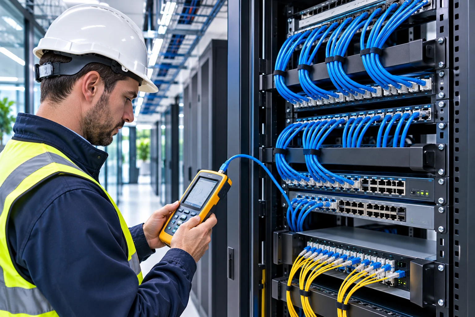
Structured cabling is a standardized physical cabling infrastructure designed to meet the communication needs of data, voice, video, and various IP-based systems in buildings and facilities. It forms the foundation of reliable network communications in a wide range of environments, from offices and data centers to hospitals, shopping malls, industrial facilities, and smart buildings.
Modern structured cabling systems are not used only to connect computers to the internet. IP security cameras, access control systems, IP phones, wireless access points, building automation systems, and various network devices can also communicate over suitable cabling infrastructure.
A well-designed structured cabling system supports data communications performance, simplifies fault detection, improves infrastructure manageability, and helps accommodate future capacity needs.
What Is Structured Cabling?
Structured cabling is the creation of communications connections within a building or campus in accordance with defined standards, topologies, and performance criteria.
With this approach, the cabling infrastructure is planned as a centrally managed system that can be reconfigured as needed, rather than as separate, disorganized connections for each device.
For example, in a multistory office building, computers, IP phones, wireless access points, and security cameras are connected to suitable distribution points. Telecommunications rooms on each floor are linked to the building’s main distribution infrastructure by copper or fiber-optic connections.
This makes it possible to manage the physical connections for different systems according to defined rules.
The primary purpose of structured cabling is to create a reliable, standards-compliant, scalable, and long-lasting physical communications infrastructure.
Why Are Structured Cabling Systems Important?
A network’s performance does not depend solely on the technical specifications of the switch, server, or security camera in use.
Cable quality, connectors, cable length, electromagnetic interference, and installation workmanship also affect overall system performance.
Incorrect cabling practices can cause the following problems:
Network connection dropouts and instability.
Data transmission errors and packet loss.
Reduced supported connection speeds.
Video transmission problems on IP cameras.
Insufficient power for PoE devices.
Unexpected restarts of network devices.
Risk of excessive heat at cable connections.
Lost time and labor when troubleshooting faults.
Standards-compliant structured cabling helps reduce these risks. However, proper cabling does not eliminate all problems with active network devices.
Key Components of a Structured Cabling System
Structured cabling infrastructure consists of passive connection components with different functions.
1. Copper Data Cables
Copper data cables are used especially in Ethernet networks to connect computers, IP cameras, IP phones, and wireless access points.
Common cable categories include Cat5e, Cat6, and Cat6A.
These cables consist of twisted conductor pairs that help reduce electromagnetic interference.
2. Fiber-Optic Cables
Fiber-optic cables transmit data using light rather than electrical signals.
They are used especially for long-distance connections, building backbones, data centers, and high-capacity network applications.
Fiber-optic cabling systems can use singlemode and multimode fiber types with different optical properties.
3. Patch Panel
A patch panel is a passive connection component that enables copper network cables to be terminated and managed in an orderly manner.
It is usually housed in network cabinets.
Using a patch panel allows connections to be labeled and documented, and linked to active network devices via patch cords.
4. Data Outlets and Keystone Jacks
Data outlets are the points at which user devices or suitable field equipment connect to the structured cabling infrastructure.
Connection modules such as keystone jacks should be selected to match the cable category.
For example, in a connection intended to deliver Cat6A performance, using Cat6A cable alone is not enough. The outlet, jack, and other connection components must also meet the relevant performance class.
5. Network Cabinets
Network cabinets allow patch panels, fiber termination units, switches, power distribution, and other network equipment to be installed in an orderly way.
The following features are important when selecting a cabinet:
Height and usable rack capacity.
Depth and equipment compatibility.
Cable entry and exit areas.
Ventilation and temperature management.
Total equipment weight.
Grounding and equipotential bonding requirements.
Ease of access for maintenance personnel.
6. Fiber-Optic Termination Panels
ODFs or suitable fiber distribution panels are used to organize and terminate fiber-optic connections.
These panels help protect fiber splices, manage connections, and organize patch cords.
For more technical information about fiber cable types, connectors, and optical testing methods, see our article What Is Fiber Optic Cable? Types, Features, and Technical Guide . You can read it here.
What Are the Types of Structured Cabling?
Structured cabling systems can be classified in different ways according to the transmission medium used and the role of the infrastructure.
Copper Structured Cabling
Copper structured cabling is widely used, particularly for horizontal Ethernet connections.
Office computers, IP phones, wireless access points and security cameras can be connected through this infrastructure.
Fiber-Optic Structured Cabling
Fiber-optic systems offer significant advantages in building backbones and connections that require high bandwidth.
Optical fiber is not affected by electromagnetic interference in the same way as copper conductors.
However, the performance of fiber connections depends on parameters such as fiber type, optical module, connector quality, splice loss and connection length.
Differences Between Cat5e, Cat6 and Cat6A Cables
In structured cabling projects, the right category should be selected according to the system’s target connection speed and operating conditions.
Feature | Cat5e | Cat6 | Cat6A |
|---|---|---|---|
Nominal category frequency | 100 MHz | 250 MHz | 500 MHz |
Common use | 1 Gigabit Ethernet | 1 Gigabit and 10 Gigabit under suitable conditions | 10 Gigabit Ethernet |
10GBASE-T support | Not a general design choice | Up to approximately 55 m under suitable conditions | up to a 100 m channel |
PoE support | With suitable products | With suitable products | With suitable products |
EMI and cable-bundle effects | Installation-dependent | Installation-dependent | Enhanced performance targets |
Usage approach | Existing basic networks | General enterprise networks | 10G and high-capacity infrastructure |
Important technical note: This table compares the general characteristics of cable categories. Whether a connection supports a given Ethernet speed depends not only on the cable category but also on the total channel length, connecting components, installation quality and measured performance.
In particular, using 10GBASE-T over Cat6 should be assessed with cable-bundle and alien crosstalk conditions taken into account.
Also, using Cat6A cable does not mean that the connection will automatically operate at 10 Gbit/s. Network devices and other connection components must also support this speed.
What Is the 90-Meter and 100-Meter Rule in Structured Cabling?
Cable length is one of the most common technical considerations in copper Ethernet cabling projects.
Two different connection models are used in standard balanced copper cabling applications with a star topology.
What Is a Permanent Link?
A Permanent Link is the permanent cabling section between fixed connection points, such as a patch panel and a telecommunications outlet.
In common standard copper horizontal cabling design, the maximum length is 90 meters.
This distance covers the fixed cabling section in the relevant connection model.
What Is a Channel?
A Channel is the total transmission path, including the permanent cabling section, suitable patch cords and equipment connection cables.
In common copper Ethernet channel design, the maximum length is 100 meters.
These two limits should not be confused.
For example, laying 100 meters of fixed Cat6 cable and adding a patch cord does not create a design that complies with the common 100-meter channel limit.
However, it cannot be said that all copper cabling applications are limited to 100 meters under all conditions. Category 8, single-pair Ethernet and specialized industrial applications may have different rules.
International Standards Used in Structured Cabling Systems
International standards play an important role in the design, implementation and testing of structured cabling systems.
ISO/IEC 11801 Series
ISO/IEC 11801 is one of the core standards series for generic structured cabling systems.
ISO/IEC 11801-1:2017, defines the general cabling requirements for customer premises.
An amendment to this standard and a related technical corrigendum were published in 2025.
Therefore, for new projects, rather than citing only the 2017 base text, ISO/IEC 11801-1:2017 and the current 2025 amendment should be considered together is necessary.
ANSI/TIA-568 Series
ANSI/TIA-568 is an important family of standards used in telecommunications cabling infrastructure.
Key documents:
Standard | Main scope |
|---|---|
ANSI/TIA-568.0-E | General telecommunications cabling |
ANSI/TIA-568.1-E | Telecommunications infrastructure in commercial buildings |
ANSI/TIA-568.2-E | Balanced copper cabling and components |
ANSI/TIA-568.3-E | Fiber-optic cabling and components |
ANSI/TIA-569-E | Telecommunications cable pathways and spaces |
ANSI/TIA-606-D | Administration and identification of cabling infrastructure |
ANSI/TIA-607-E | Telecommunications grounding and bonding infrastructure |
These standards cover different technical subjects. A product’s compliance with a particular TIA standard does not automatically mean that the entire cabling project complies with standards.
IEC 61935-1
IEC 61935-1:2019 defines reference measurement methods for testing installed balanced copper cabling systems and accuracy requirements for field-test instruments.
This standard is important for verifying not only the physical continuity of a cable connection but also its transmission performance.
How Is Structured Cabling Installed?
Professional structured cabling involves more than pulling and terminating cables.
A successful project encompasses site surveys, design, implementation, testing and documentation.
1. Site Survey and Needs Analysis
The existing premises and the network systems to be used are analyzed in the first phase.
The following questions are considered:
How many users and active network devices will be connected?
How many IP cameras and access points will there be?
Which devices will be powered over PoE?
How many floors does the building have, and how many distribution areas are needed?
What are the target network speeds?
Is fiber-optic connectivity required between buildings?
What capacity increases are expected in the future?
Planning cabling based solely on port count before completing this analysis may lead to significant infrastructure changes later.
2. Determining the Cabling Topology
Structured cabling systems are generally arranged in a hierarchical star topology.
Depending on the building’s architecture, a main distribution area, building backbone, floor distribution areas, and horizontal cabling sections are established.
This arrangement makes it easier to manage connections and locate faults by area.
3. Preparing Cable Routes
Data cables are routed through suitable cable trays, ducts, conduits, or other support systems.
Cables must not be exposed to mechanical damage, sharp edges, excessive pulling force, or inappropriate bends.
If power and data cables share a route, separation and protection requirements should be assessed in accordance with the applicable standards and site conditions.
It should not be assumed that there is one fixed separation distance applicable to every project.
4. Cable Termination and Connections
Copper data cables are terminated at a suitable patch panel, modular jack, or relevant connector.
In common RJ45/8P8C connections, the T568A and T568B termination schemes are used.
For applications requiring a straight-through connection, using the same scheme at both ends is important for correct pair mapping.
During termination, pairs must not be untwisted more than necessary, and the manufacturer’s installation instructions must be followed.
5. Labeling and Documentation
Identifying all connections is important for the long-term management of the cabling infrastructure.
For example, the following information can be recorded for each cable connection:
Source cabinet.
Patch panel number.
Port number.
Destination data outlet or device point.
Cable category.
Test result.
Cable route.
and similar information.
It is important for the labeling system to comply with the administrative standard used in the project.
The Importance of Structured Cabling in PoE Systems
Power over Ethernet (PoE) is a technology that enables compatible network devices to receive electrical power over an Ethernet cable alongside data communications.
PoE is widely used with IP security cameras, wireless access points, IP phones, and compatible access-control equipment.
For devices powered by PoE, not only the cable’s data-transmission performance but also its electrical characteristics become important.
What to Consider When Selecting Cables for PoE
Material and gauge of the copper conductors.
Cable length and resistance values.
Resistance unbalance between pairs.
Temperature rise in the cable bundle.
Patch panel and connector compatibility.
The switch’s total PoE power budget.
The camera’s actual power consumption.
Additional loads such as night-time IR illumination, motors, or heaters.
Conductors such as CCA (Copper Clad Aluminum) —aluminum conductors clad in copper—should not be considered direct equivalents of standards-compliant solid copper data cables.
Conductor resistance and temperature rise become more important, particularly in high-power PoE applications.
A PoE-enabled switch providing a certain power capacity does not mean that the same level of power will be available to the device without cable losses.
Therefore, PoE design must account for the cabling infrastructure, power supply, and device loads together.
What Are Structured Cabling Tests and Certification?
Once installation is complete, the physical connections and transmission performance of cabling systems must be verified.
However, not all test instruments measure the same range of parameters.
Cable Continuity Testing
Basic cable testers help determine whether conductors are correctly mapped and identify some connection faults.
For example, open circuits, short circuits, and miswiring can be detected.
However, passing a continuity test does not prove that a cable meets Cat6 or Cat6A performance requirements.
Cable Certification Testing
Professional cabling certification instruments measure the electrical transmission characteristics of a link in accordance with the selected test standard.
Measurable parameters may include:
Wiremap (conductor mapping).
Cable length.
Insertion Loss.
NEXT (near-end crosstalk).
Return Loss.
Relevant performance parameters such as ACR-N and ACR-F.
Propagation Delay.
Delay Skew.
Additional crosstalk and resistance parameters where required.
may be included.
The correct link model and target performance class must be selected on the test instrument.
Permanent Link and Channel Testing
The Permanent Link model is generally used to verify the permanent infrastructure in new horizontal cabling projects.
A Channel test can be used to assess the performance of the entire channel, including the patch cords used in the connection.
These two tests represent different connection scopes, and one should not be used arbitrarily in place of the other.
Why Is a Certification Report Necessary?
A certification report helps document that the installed cabling infrastructure has been measured against specific test criteria.
It is useful for a handover report to include the following information:
Connection or cable identifier.
Category or class tested.
Standard and test model used.
Measurement date.
Test instrument and calibration information.
Measurement results and PASS/FAIL status.
Electronic records of test data, where applicable.
A cable being marked Cat6A is one thing; the installed link being tested against Cat6A criteria and achieving a valid result is another.
This distinction is important, particularly in enterprise network and electronic security projects.
Why Is Structured Cabling Important in CCTV Systems?
The quality of the physical infrastructure matters because IP camera systems transmit video data over a network.
Unsuitable connections can cause interruptions in camera access and video transmission problems.
The following criteria should be assessed to ensure correct cabling in CCTV projects:
Connection length between the camera and switch.
IP camera data rate and network capacity.
PoE power requirements.
Cable category and connection components.
Durability of outdoor cables.
Electrical and electromagnetic conditions.
Lightning and surge risks.
Need for a fiber-optic backbone.
Location and capacity of the network cabinet.
Testing and documentation requirements.
The use of a fiber-optic backbone may be considered, particularly in campus, factory, port, logistics facility, and large perimeter-security projects.
Nevertheless, fiber-optic connectivity is not required for every IP camera. The design should take distance, network capacity, electrical risks, and costs into account.
What Is the Difference Between Structured Cabling and ELV Systems?
Structured cabling is one component of the broader low-voltage and electronic communications infrastructure.
Low-voltage systems can include various technologies such as CCTV, fire detection, burglar alarms, access control, intercom, public address, and building automation.
Structured cabling, by contrast, is primarily concerned with standardized data and communications connection infrastructure.
For example:
An IP camera is an electronic security device.
An Ethernet cable and its associated termination components are part of structured cabling in an appropriate project.
A network switch is an active network device that enables communication.
An NVR is a component of the video recording and management system.
This distinction is important for correctly defining project scopes and technical responsibilities.
To learn about other components of low-voltage systems, What Are Low-Voltage Systems? Types and Technical Guide you can read our article titled
The Most Common Structured Cabling Mistakes
Using Non-Standard-Compliant Cable
Low-quality cables or cables whose technical specifications have not been verified may fail to deliver the expected transmission performance.
Selecting the Wrong Cable Category
Choosing a category without assessing future bandwidth requirements may increase the need to upgrade the infrastructure.
Unsuitable Cable Routing
Excessive bending, high pulling force, mechanical pressure, and unsuitable routes can affect cable performance.
Incorrect Termination
Untwisting twisted pairs more than necessary or using unsuitable connectors can cause crosstalk and other transmission problems.
Failing to Calculate PoE Power Requirements
Failing to account for total consumption and cable losses in high-power network devices can adversely affect connection continuity.
Handing Over the System Without Testing
It is not enough for the cable merely to provide a connection.
Suitable field certification tests should be performed, particularly in projects with performance guarantees.
Insufficient Labeling and Documentation
Failure to record port numbers, cable identifiers, and routes complicates future maintenance.
Technical Checklist for a Structured Cabling Project
Checklist heading | Item to be checked |
|---|---|
Project analysis | Device count and capacity requirements |
Cable category | Target network speed and class compliance |
Cable length | Permanent Link and Channel limits |
Cable route | Mechanical protection, separation, and bends |
Patch panel | Category and connection compatibility |
Data outlet | Correct termination and labeling |
Cabinet | Capacity, ventilation, and access |
Fiber optics | Fiber type, optical budget, and termination |
PoE | Power budget, voltage drop, and heating |
Testing | Appropriate standard and test instrument |
Certification | Measurement reports |
Documentation | Port, cable, and route records |
This checklist has been prepared to assist with project planning and technical acceptance activities.
The final engineering design should be developed in consideration of applicable standards, manufacturer instructions, and the project’s specific requirements.
Frequently Asked Questions About Structured Cabling
What is structured cabling used for?
Structured cabling provides the physical infrastructure for reliable data communication between computers, IP cameras, IP phones, and other compatible network devices. It helps standardize and manage connections.
Should you choose Cat6 or Cat6A?
The choice depends on the target data rate, cable length, PoE load, installation conditions, and future capacity needs. Cat6A is an important option for new projects targeting 10GBASE-T support within the standard 100-meter channel. However, it is not mandatory for every application.
What is the maximum cable length in structured cabling?
In the common four-pair copper Ethernet horizontal cabling model, the Permanent Link length is 90 meters and the total Channel length is 100 meters. Different limits may apply to special cabling topologies and other types of Ethernet.
Which is better: fiber-optic cable or copper cable?
The two technologies have different advantages. Copper cable can provide data and PoE power transmission over suitable distances. Fiber-optic cable may offer advantages for high-capacity, long-distance connections. The choice should be based on project requirements.
Is certification of structured cabling required?
Certification helps verify whether installed links meet the specified transmission performance. It may be required under project specifications, quality commitments, or acceptance requirements. It should not be assumed that every cable must be legally certified under all circumstances.
How many years does structured cabling last?
The service life of structured cabling depends on product quality, installation conditions, environmental factors, maintenance, and technological needs. The fact that a physical cable continues to work does not mean it will support all future data rates.
Conclusion
Structured cabling is one of the fundamental components of the data communications infrastructure of modern buildings and electronic security systems.
In a successful structured cabling project, selecting the right cable category alone is not enough. Connection topology, cable lengths, the fiber backbone, PoE requirements, installation quality, cable testing, and documentation must all be assessed as a whole.
A standards-compliant, tested, and properly documented structured cabling infrastructure supports network reliability, makes it easier to identify technical faults, and provides a more manageable foundation for future system expansions.
It should be remembered that the quality of physical cabling is an integral part of system performance, particularly in IP camera systems, access control, building automation, and enterprise network infrastructure.