
What Should a Camera Pole Be Like? CCTV Pole Standards and Technical Selection Guide
How should a security camera pole be selected? We examine the criteria for CCTV poles—including height, diameter, wall thickness, galvanizing, wind load, vibration, concrete foundations, anchors and grounding—in light of relevant international standards. We explain the points to consider when technically selecting fixed and PTZ camera poles.
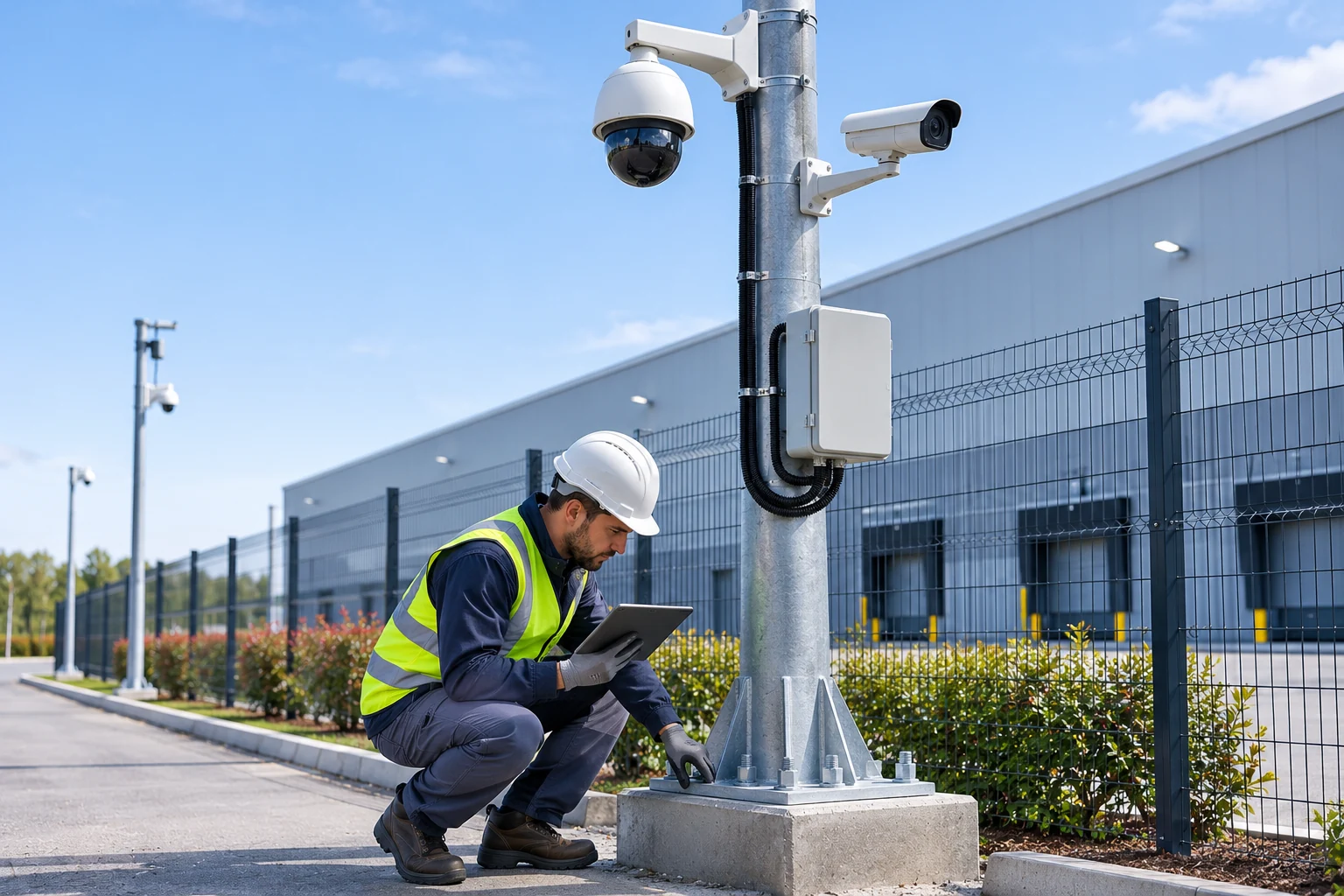
Security camera poles are important structural components that enable cameras in outdoor CCTV systems to be positioned correctly and supported securely. Used at factories, ports, car parks, logistics facilities, power plants and perimeter-security sites, camera-pole design affects both image quality and the system’s long-term reliability.
An unsuitable camera pole may vibrate in the wind, alter the camera’s field of view, or develop mechanical problems at connection points over time. An inadequate foundation and anchor design can jeopardize the structural safety of the support.
Therefore, camera-pole selection should not be based solely on height, pipe diameter or wall thickness. Camera weight, wind load, mounting brackets, pole stiffness, foundation conditions and the relevant structural design standards should be assessed together.
What Is a Camera Pole?
A camera pole is a supporting structure that enables security cameras to be positioned securely at a specified height and with a suitable field of view.
Usually made of steel, camera poles can support fixed cameras, PTZ cameras, thermal cameras, lighting equipment and communication devices, depending on the application.
The main functions of a CCTV pole are:
Keep the camera at the intended viewing height.
Support the weight of the camera and mounting brackets.
Provide structural strength under wind and environmental loads.
Keep camera vibration within acceptable limits.
Protect cable and power connections.
Allow safe access for maintenance and servicing.
Be suitable for long-term outdoor use.
An important distinction should be made here: a pole being structurally safe does not mean it is sufficiently stiff for imaging performance.
A pole may withstand wind loads without toppling or undergoing permanent deformation, yet move enough to affect the camera image.
What Types of Camera Poles Are There?
Camera poles differ according to their support structure, mounting method and the type of camera they are used with.
Fixed Camera Poles
These supports are used for cameras such as bullet cameras and fixed domes.
They are generally preferred at perimeter fences, access roads, car parks and security points around buildings.
PTZ Camera Poles
PTZ cameras offer horizontal and vertical movement as well as optical zoom.
The pole’s vibration behavior becomes important, particularly in applications using high optical zoom.
Even small angular movements can cause noticeable shifts in images of distant objects.
For this reason, the support stiffness and dynamic behavior of PTZ camera poles should be assessed separately.
Tapered and Polygonal Camera Poles
These are poles whose cross-section varies along their height.
When properly designed, they can offer advantages in material use and structural performance.
However, being tapered or polygonal does not in itself mean that a pole has sufficient strength.
Flanged Camera Poles
These systems use a steel flange plate at the pole base, secured to a concrete foundation with anchor elements.
With proper design and installation, they can make maintenance and replacement easier.
Hinged or Lowering Camera Poles
These poles have a special mechanism that allows camera equipment to be lowered closer to ground level.
They may be considered in locations where maintenance access is difficult or the risk of working at height is high.
However, the mechanism’s load capacity, locking and safety require special design.
How Tall Should a Camera Pole Be?
When determining camera-pole height, the goal should not be merely to capture a wide area.
Mounting height should be assessed in conjunction with the following parameters:
The camera’s imaging purpose.
Distance to the target being monitored.
Camera resolution and lens.
Target pixel density.
Obstructions in the line of sight.
Movement of vehicles and people.
Risk of physical tampering.
Wind load and support vibration.
Service and maintenance access.
Examples of Camera-Pole Heights by Application
Pole height | Potential application |
|---|---|
3–4 metres | Entrance points and close-range surveillance |
4–6 metres | Open car parks and facility perimeters |
6–8 metres | Larger perimeter-security areas |
8–10 metres | Special wide-area or PTZ applications |
Over 10 metres | High supports requiring specialist engineering |
These heights are not values mandated by standards. They are provided solely to illustrate possible scales of application.
For example, a camera mounted at a height of 8 metres may be able to view a distant area, but that does not mean it will record a person’s face at an entrance with sufficient detail.
Therefore, the viewing target and pixel density should be calculated together when determining camera height.
For detailed information about field of view, lens selection and pixel-density calculations, What Is DORI Analysis in Camera Systems? How Is It Performed? please see our technical article titled
How Are Camera-Pole Diameter and Wall Thickness Determined?
One question frequently asked in camera-pole projects concerns the diameter and wall thickness of the pipe to be used.
However, there is no single pipe diameter or sheet thickness that applies to every CCTV project.
The following characteristics should be examined when selecting the pole cross-section:
The pole’s total height.
The combined mass of the camera and accessories.
The surface area of the cameras exposed to wind.
The distance of the camera brackets from the pole axis.
The mechanical properties of the pole material.
The cross-section’s bending and torsional strength.
The pole’s displacement and vibration behavior.
The base plate and anchoring system.
Foundation and ground conditions.
Corrosion effects and design life.
Are Pipe Diameter and Wall Thickness the Same Thing?
No.
Pipe diameter and wall thickness are parameters that affect the mechanical behavior of a cross-section in different ways.
For example, even if two different camera poles have the same outside diameter, differences in wall thickness affect load capacity, stiffness and weight.
Similarly, when two pipes with the same wall thickness have different diameters, their bending stiffness can also differ significantly.
The second moment of area of a circular hollow steel section is expressed as follows:
Here:
\(I\): The second moment of area of the cross-section
\(D\): The pipe’s outside diameter
\(d\): The pipe’s inside diameter
This expression shows how cross-sectional geometry affects bending stiffness. However, by itself, it does not prove that a CCTV pole is safe.
In actual projects, material strength, buckling, connection conditions, load combinations and dynamic effects must also be assessed.
Camera-Pole Dimensions in Official Technical Specifications
In Türkiye, technical specifications issued by some public institutions define different pole dimensions for fixed and moving cameras.
For example, the following sample values appear in an accessible technical specification document issued by the Ministry of Culture and Tourism:
Characteristic | Fixed-camera pole | Moving-camera pole |
|---|---|---|
Pole height | 4 m | 6 m |
Pole diameter | 180 mm | 300 mm |
Minimum sheet thickness | 3 mm | 4 mm |
Surface protection | Hot-dip galvanizing | Hot-dip galvanizing |
These dimensions are project/product specifications from a particular public-sector technical specification. They should not be interpreted as universal dimensions that all camera poles must meet.
Moreover, the fact that these dimensions appear in a specification does not mean that a structural calculation is unnecessary for wind, ground and camera loads at another site.
Why Is Wind Load Important for Camera Poles?
Camera poles in outdoor areas may be continuously exposed to wind.
Wind exerts force not only on the pole shaft but also on camera housings, brackets, lighting equipment and other mounted devices.
Wind can create a bending moment at the pole base and, in some configurations, torsional effects.
Parameters Affecting Wind Load
Regional design-wind data.
Terrain roughness and surrounding development.
Pole height.
Wind-exposed area of the camera and accessories.
Aerodynamic shape of the equipment.
Bracket length.
The pole’s natural vibration characteristics.
Turbulence and dynamic effects.
A simplified dynamic-pressure approach can be expressed as follows:
Here, \(q\) represents dynamic pressure, \(\rho\) air density, and \(V\) wind speed.
This relationship shows only the underlying physical principle. It is not, on its own, a wind-load calculation compliant with regulations.
Actual design must apply the relevant standard’s provisions for velocity profiles, load factors, terrain and height effects, aerodynamic coefficients and dynamic behavior.
Which Standard Is Used for Wind Load?
EN 1991-1-4 is one of the Eurocode references used for wind actions on structures.
Depending on the structural type of the pole, the EN 40 series or other standards such as EN 1993-3 may also be considered.
However, it should not be assumed that every camera pole falls directly within the scope of EN 40.
Whether the pole is designed as a lighting column, a camera-support mast or a special steel structure affects the choice of applicable scope.
The fact that UK highway-infrastructure design documents have separate design references for CCTV masts and lighting columns also demonstrates the importance of this distinction.
How Can Vibration Be Prevented in PTZ Camera Poles?
When PTZ cameras operate at high optical zoom levels, support vibrations can become more noticeable.
Even a very small angular movement of the pole can cause a noticeable shift in the image of a distant object.
For example, for a target 100 metres away, an angular movement of about 0.1 degrees corresponds geometrically to a shift of about 17 centimetres on the target plane.
This example shows why small angular movements matter in long-distance imaging applications.
Factors Affecting Vibration
Bending stiffness of the pole shaft.
Overall pole height.
Bracket length.
Weight and mass distribution of the PTZ camera.
Wind-induced vibration.
The pole’s natural frequencies.
The behavior of anchor and foundation connections.
The vibration characteristics of the camera and its mounting brackets.
Using a thicker tube alone may not be enough to reduce vibration.
It may be necessary to change the cross-sectional geometry, shorten the cantilever, reinforce the supporting structure, or opt for a different pole design.
Image stabilization technologies also cannot always compensate for inadequate structural stiffness.
In professional PTZ applications, acceptable limits for support movement should be determined according to the actual imaging requirements of the camera and lens to be used.
What Should a Camera Pole Foundation Be Like?
The safe operation of a camera pole depends on the concrete foundation and anchoring system as much as it does on the pole itself.
Foundation design is not intended merely to support the total weight of the pole. Wind, bending moments, horizontal forces, soil bearing capacity, and other load effects must also be assessed.
Criteria to Check for a Camera Pole Foundation
Soil bearing capacity.
Pole height and weight.
Wind-induced overturning effects.
Concrete grade.
Foundation dimensions and reinforcement arrangement.
Diameter, grade, and placement of anchor bolts.
Anchor embedment and edge distances.
Base plate thickness.
Transfer of shear forces.
Groundwater and environmental conditions.
Seismic effects where required.
How Many Centimeters Deep Should a Camera Pole Foundation Be?
There is no single foundation dimension that applies to all camera poles.
For example, the foundation requirements for a lightweight 4-meter pole may differ from those for an 8-meter pole carrying multiple PTZ cameras and communications equipment.
Foundation size, concrete volume, and anchor arrangement should be determined through project-specific structural and geotechnical assessments.
Recommending standard foundation dimensions such as 50 × 50 × 50 cm or 100 × 100 × 100 cm based solely on pole height is not a reliable engineering approach.
How Should Anchor Bolts Be Selected?
Anchor bolts must safely withstand the forces transferred from the base plate to the foundation.
Selection should take into account not only bolt diameter but also strength grade, placement, tensile and shear loads, concrete strength, anchor type, and installation method.
Bolts should be tightened using the torque and application conditions specified by the manufacturer or engineering design.
Galvanizing and Corrosion Protection for Camera Poles
Because CCTV camera poles are used outdoors for extended periods, corrosion resistance is an important technical criterion.
The risk of corrosion may increase, particularly in coastal areas, industrial facilities, ports, and regions with high humidity.
What Is Hot-Dip Galvanizing?
Hot-dip galvanizing is the process of forming a protective coating by immersing properly prepared steel parts in a bath of molten zinc.
ISO 1461:2022 defines the general properties and test methods for hot-dip galvanized coatings applied to fabricated iron and steel products.
When assessing galvanizing on camera poles, the following should be checked:
Whether the pole was coated after manufacture.
Whether the relevant standard is suitable for the product.
Coating thickness and surface integrity.
Protection of welded areas.
The condition of cable-entry holes.
Protection of cut or machined surfaces.
Corrosion risk in the application environment.
should be assessed.
Galvanizing does not remedy mechanical deficiencies in the welding or connection design.
Additional paint systems or other protection methods may be required in coastal areas and highly corrosive environments.
Grounding and Lightning Protection for Camera Poles
Electrical safety, network infrastructure, and lightning effects must be considered together for metal camera poles.
Tall poles in open areas, outdoor cables, and metal supporting structures may pose particular risks.
Should a Camera Pole Be Grounded?
The pole’s electrical connection and protection arrangement should be designed according to the power supply system, electrical classification of the equipment used, and the facility’s grounding infrastructure.
The metal body may need to be incorporated into an appropriate protective and equipotential-bonding system.
However, driving an arbitrary grounding rod or connecting the pole to an independent grounding electrode does not provide a safe and adequate solution in every case.
The electrical safety of the pole, camera, power supply, and communications connections should be addressed as a whole.
Lightning Protection
The 2024 editions of the IEC 62305 series are important references for lightning protection.
These standards cover:
Lightning risk assessment.
Structural protection.
Touch and step voltage risks.
Protection of electrical and electronic systems.
among other topics.
The need for suitable lightning protection arrangements and surge protective devices for outdoor camera poles should be determined through risk assessment.
The connection and grounding arrangement of SPD devices used on PoE network connections is also important.
The presence of an SPD device does not mean that the camera is completely protected against a direct lightning strike.
How Should Cables and Junction Boxes Be Arranged on a Camera Pole?
In professional camera-pole installations, the aim should be to route cables under mechanical protection wherever possible.
The presence of a cable route inside the pole does not mean that the cable is automatically protected against every kind of damage.
The following points should be considered in particular:
Removing sharp edges from cable-entry holes.
Protecting the cable with suitable glands and feed-through components.
The risk of water pooling and condensation on interior surfaces.
Securing cables inside the pole.
Proper routing of data and power lines.
Physical security of the service hatch and junction box.
UV and moisture resistance of outdoor cables.
Access to electrical protection components.
An appropriate IP protection rating under IEC 60529 should be selected for outdoor junction boxes.
Ratings such as IP66 or IP67 indicate the enclosure’s protection characteristics under specified test conditions; they do not mean that incorrectly installed glands and connections will provide the same protection.
What Standards Apply to Camera Poles?
It should not be assumed that a single standard covers all technical requirements for camera-pole design.
Depending on the type of pole, its location, and project requirements, structural, environmental, and electronic safety standards are assessed together.
Standard or regulation | Relevant technical subject |
|---|---|
EN 1991-1-4 | Calculation of wind effects |
EN 1993-3 | Design of steel towers and masts where applicable |
EN 40 series | Lighting columns within its scope |
ISO 1461:2022 | Hot-dip galvanized coatings |
IEC 62305:2024 series | Lightning protection |
IEC 60529 | IP protection ratings |
IEC 62676-4:2025 | Application guidelines for video surveillance systems |
Turkish Principles for the Design of Steel Structures | Structural steel design within its scope |
Turkish Building Earthquake Code | Seismic effects within its scope |
Is EN 40 Mandatory for Camera Poles?
EN 40 is a series of standards developed primarily for lighting columns.
It cannot be said that all poles fitted with cameras fall directly within the scope of EN 40.
For camera-support masts and custom steel poles in particular, the product classification, structural design approach, and applicable specifications should be assessed.
Does IEC 62676-4:2025 Specify Pole Dimensions?
No.
IEC 62676-4:2025 is an application guideline for the planning, design, installation, testing, commissioning, and maintenance of video surveillance systems for security applications.
It is not a pole-design standard that directly specifies a diameter, wall thickness, foundation dimension, or anchor-bolt size applicable to all camera poles.
The mechanical design of a camera pole requires the relevant structural standards and engineering calculations specific to the project.
How Should Fixed and PTZ Camera Poles Be Compared?
Assessment | Fixed-camera pole | PTZ-camera pole |
|---|---|---|
Imaging | Fixed field of view | Movable, zoom-capable view |
Load | Camera and accessories | Camera, bracket, and related accessories |
Wind | Must be calculated | Must be calculated |
Vibration sensitivity | Depends on the imaging task | May be more noticeable at high zoom |
Stiffness | Must be determined according to the task | Dynamic behavior is also important |
Cantilever | Suitable load transfer | Moment and vibration effects may be critical |
Foundation | Must be determined by structural design | Structural design and, where necessary, dynamic design |
Maintenance | Safe access | Safe access and movement control |
This comparison does not mean that all PTZ poles must be larger than fixed-camera poles.
The right support should be selected according to the actual loads and imaging conditions of the equipment used.
Common Camera Pole Installation Errors
Selecting a Pole Without Structural Calculations
Selecting a pole solely on the basis of dimensions used in previous projects is not reliable.
Choosing Foundation Dimensions Arbitrarily
Constructing a foundation without assessing the soil, wind, and overturning effects can pose a structural risk.
Mounting a Heavy PTZ Camera on an Inadequate Cantilever
Even if the camera appears lightweight, the cantilever length and wind effects can create significant moments at the connection point.
Damaging the Galvanized Coating
Cutting, drilling, or welding during installation can damage the protective coating.
Using Unsuitable Anchors
Incorrect selection of the anchor grade, embedment depth, or connection arrangement can affect the pole’s safety.
Leaving Cables and Connections Exposed
Exposure of camera connections to water and mechanical damage can cause long-term failures.
Failing to Conduct Vibration Testing
A good image in still daytime conditions does not guarantee the same image stability in windy conditions.
For other installation errors related to this subject, 16 Common Camera Installation Errors and Their Solutions see our guide titled
Camera Pole Installation and Acceptance Checklist
Check item | What to check |
|---|---|
Camera task | Target distance, lens, image detail |
Pole height | Suitability of field of view and access |
Pole cross-section | Diameter, wall thickness, material grade |
Structural calculation | Wind, bending, torsion, and vibration |
Foundation | Approval of soil and foundation design |
Anchors | Placement, strength, and tightening checks |
Galvanizing | Coating quality and damage |
Cantilever | Camera compatibility, load, and movement |
Grounding | Protection and equipotential bonding |
Lightning | Risk Assessment and SPD |
Wiring | Mechanical and Environmental Protection |
Junction Box | IP Rating and Sealing |
Image Testing | Day, Night, and Zoom Performance |
Documentation | Structural Report, Drawings, and Acceptance Record |
This checklist is prepared to support professional site handover. It does not replace structural calculations and structural approvals that must be carried out by an authorized engineer.
Frequently Asked Questions About Camera Poles
How tall should a camera pole be?
The height of a camera pole should be determined by taking into account the viewing purpose, target distance, camera lens, physical surroundings, and structural loads. There is no single height that applies to every camera.
What is the minimum thickness of a camera pole, in millimeters?
There is no single minimum wall thickness that applies to all CCTV poles. The material and cross-section should be selected according to the scope of the applicable standard, pole height, loads, and structural calculations.
Should a camera pole be galvanized?
Galvanized steel poles are one of the common and suitable solutions for outdoor use. However, whether galvanizing is mandatory depends on the project specifications and product requirements. The protection method should be selected according to environmental corrosion conditions.
How many centimeters should the concrete foundation for a camera pole be?
The foundation dimensions should be calculated based on the pole’s height and weight, as well as wind, anchoring, concrete, and ground conditions. There is no single foundation size that applies to all poles.
Are structural calculations required for a camera pole?
The structural safety of the pole must be verified in accordance with the relevant design principles. The scope and method of documentation depend on the pole type, installation, applicable regulations, and project requirements.
Why does a PTZ camera vibrate on a pole?
Wind, insufficient pole stiffness, a long cantilever, loose connections, or the support’s natural vibration characteristics can cause this problem. High optical zoom can make the effect of vibration on the image more pronounced.
Which standard applies to a camera pole?
No single standard covers all pole designs. Different standards may be considered together for structural steel design, wind loads, corrosion protection, lightning safety, and CCTV applications.
Conclusion
A camera pole is not merely mechanical mounting equipment for a CCTV system; it is a fundamental support component that affects imaging performance and system reliability.
When selecting the right camera pole, physical dimensions such as height, pipe diameter, and wall thickness should be considered alongside wind load, vibration behavior, concrete foundation, anchoring, corrosion resistance, and electrical safety criteria.
In PTZ systems that use high optical zoom in particular, the stiffness of the support is critical to image stability.
In professional camera-pole applications, the goal is not simply to position the camera at a safe height; it is to create a structurally safe, maintainable support system that enables the camera to sustain its intended imaging performance under changing environmental conditions.